
What are the common protection circuits for LED switching power supplies?
2022-02-17(1614)views
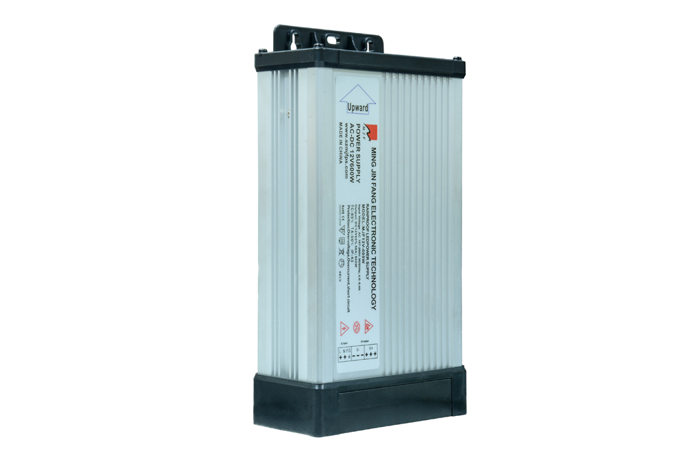
The LED switching power supply is controlled by the circuit to conduct high-speed on and off. It converts direct current into high-frequency alternating current to transform the converter to generate one or more sets of voltages required. And LED switching power supply In addition to being stable, efficient and reliable, various circuit Protection measures must also be carefully designed to avoid rapid and effective protection of switching power supply circuits and loads under complex environmental conditions. So what are the common protection circuits for LED switching power supplies? Let's follow the editor of Mingjinfang to take a look!

1. Overheat protection circuit
The high integration and light weight and small size of the switching regulator in the DC LED switching power supply greatly improve the power density per unit volume. If the requirements of the device on its working environment temperature are not correspondingly increased, the circuit performance will inevitably deteriorate, and the components will fail prematurely. Therefore, an overheating protection circuit should be set up in the high-power DC LED switching power supply.
In this paper, the temperature relay is used to detect the temperature inside the power supply device. When overheating occurs inside the power supply device, the temperature relay will act, so that the alarm circuit of the whole machine is in an alarm state, and the power supply is in an alarm state. overheating protection. As shown As shown in 4(a), the P-type control gate thermal thyristor is placed near the power switch triode in the protection circuit. According to the characteristics of TT102 (determined by the Rr value, the conduction temperature of the device is determined. The larger the Rr, the lower the conduction temperature. ), when the case temperature of the power tube or the temperature inside the device exceeds the allowable value, the thermal thyristor is turned on, causing the LED to light up to give an alarm. If it cooperates with a photocoupler, the alarm circuit of the whole machine can be activated to protect the LED switching power supply. The circuit can also be designed as shown in Figure 4(b), used as the overheat protection of the power transistor, the base current of the transistor switch is bypassed by the N-type control gate thermal thyristor TT201, the switch is turned off, and the collector current is cut off, prevent overheating.
2. Overvoltage protection circuit
The overvoltage protection of the switching regulator in the DC LED switching power supply includes input overvoltage protection and output overvoltage protection. If the voltage of the unregulated DC power supply (such as batteries and rectifiers) used by the switching regulator is too high, it will cause the switching regulator to not work properly, or even damage the internal devices. voltage protection circuit. Figure 3 is a protection circuit composed of transistors and relays. In this circuit, when the voltage of the input DC power supply is higher than the breakdown voltage value of the Zener diode, the Zener diode breaks down, and a current flows through the resistor R, so that the The transistor T is turned on, the relay operates, the normally closed contact is disconnected, and the input is cut off. The polarity protection circuit of the input power supply can be combined with the input overvoltage protection to form a polarity protection identification and overvoltage protection circuit.
3. Overcurrent protection circuit
In the DC LED switching power supply circuit, in order to protect the adjustment tube from being burned when the circuit is short-circuited and the current increases. The basic method is that when the output current exceeds a certain value, the adjustment tube is in a reverse bias state, thereby cutting off and automatically cutting off the circuit current. The overcurrent protection circuit consists of transistor BG2 It is composed of voltage divider resistors R4 and R5. When the circuit is working normally, through the pressure action of R4 and R5, the base potential of BG2 is higher than the emitter potential, and the emitter junction bears the reverse voltage. So BG2 In the cut-off state (equivalent to open circuit), it has no effect on the voltage regulator circuit. When the circuit is short-circuited, the output voltage is zero, the emitter of BG2 is equivalent to grounding, then BG2 It is in a saturated conduction state (equivalent to a short circuit), so that the base and emitter of the adjustment tube BG1 are close to a short circuit, and in an off state, the circuit current is cut off, so as to achieve the purpose of protection.
4. Soft start protection circuit
The circuit of the switching regulator is more complicated, and the input end of the switching regulator is generally connected to an input filter with a small inductance and a large capacitance. At the moment of power-on, a large surge current will flow through the filter capacitor, and this surge current can be several times the normal input current. Such a large inrush current can melt the contacts of ordinary power switches or relays and blow the input fuse. In addition, inrush current can damage capacitors, shortening their life and failing prematurely. For this reason, a current-limiting resistor should be connected at startup, and the capacitor should be charged through this current-limiting resistor. In order to prevent the current limiting resistor from consuming too much power and affecting the normal operation of the switching regulator, a relay is used to automatically short-circuit it after the startup transient process, so that the DC power supply directly supplies power to the switching regulator , this circuit is called the "soft start" circuit of DC LED switching power supply .
At the moment when the power is turned on, the input voltage charges the capacitor C through the rectifier bridge (D1~D4) and the current limiting resistor R1 to limit the inrush current. When the capacitor C is charged to about 80% of the rated voltage, the inverter works normally. The trigger signal of the thyristor is generated by the auxiliary winding of the main transformer, which makes the thyristor conduct and short-circuit the current limiting resistor R1, and the LED switching power supply is in a normal operation state. In order to improve the accuracy of the delay time and prevent the relay from shaking and oscillating, the delay circuit can use the circuit shown in Figure 3(b) to replace the RC delay circuit.
The above mentioned common protection circuits for LED switching power supply are shared here. Compared with traditional DC power supply, LED switching power supply has the advantages of small size, light weight and high efficiency. high advantage. In addition, the development and application of LED switching power supply is of great significance in saving energy, saving resources and protecting the environment.
Latest News
-

What factors should be considered when choosing a switching power supply?
A large production enterprise needs a lot of intelligent eq...
-
What are the conversion methods of switching power supply?
The so-called switching power supply, as the name implies, ...
-

company profile
Shenzhen Mingjinfang Electronic Technology Co., Ltd. was est...
-
The selection of LED switching power supply should consider many factors
1. Select the appropriate input voltage range: Take AC input...
0755-27221809
Service Hotline:0755-27221809
Telephone:181 2882 0589
Fax:0755-27479339
Email:szmjfps@163.com
Address:3rd Floor, Building A, Shengfeng Industrial Park, Helishan Road, North Yanchuan, Songgang, Baoan District, Shenzhen


 0755-27221809